Air bending long on the press brake, Part II
In Part I, we learned how the 20% rule—stating that an air-bent radius forms as a percentage of the die opening—works well on short bend lengths. However, as we increase the length of the bend, that rule flies right out the window as the inside bend radius gradually changes to one that matches the punch nose radius.
Why this happened boils down to applied tonnage. That, however, is only a vague description of what is really going on, and we are still a long way from being able to predict what the radius might ultimately be.
As we delve deeper into the radius transition in air bending—from one that’s a percentage of the die opening to one that follows the punch nose radius—we are confronted with a complex web of factors, including the influence of bending speed, temper, ductility, and stress on the radius as it makes its transition. For those forming sheet metal, it’s a fascinating topic worthy of a deeper dive.
The Abyss
It is said that “if you stare into the abyss long enough, the abyss will stare back.” As we discover more about how the radius behaves in air bending, you may begin to feel that abyss staring back at you. Don’t let that stare keep you from finishing this journey.
Yes, we are getting in deep and going deeper, but after learning about a few more concepts—including what they are and how they apply—the journey through the weeds should be easy. These concepts include ductility and forming pressure.
Ductility Basics
Ductility measures a material’s ability to withstand significant plastic deformation before it ruptures or fails. In simple terms, it is the metal’s ability to be stretched or deformed into a new shape without breaking.
Ductility can be expressed as elongation, which is how much sheet metal can stretch under a tensile load before breaking. The higher the elongation value, the higher the level of ductility.
Other properties related to ductility include tensile strength, or the amount of stress a material can withstand while being stretched; and yield strength, the amount of stress required for a material to start deforming plastically and stay bent.
Low- Versus High-Pressure Forming
Consider forming 26-ga. cold-rolled steel with a 60,000-PSI tensile strength—this time under low pressure. In this case, the inside bend radius will primarily depend on the die’s width.
What constitutes “low-pressure forming” depends on the material type and strength. The idea here can be defined as the forming tonnage required to form a bend length of 1 ft. over a proper die opening. The material will float a bend radius as a percentage of the die opening. However, as we look back at the moment of bending (described last month), we see that the tonnage required to form a piece of sheet metal increases exponentially with bending length.

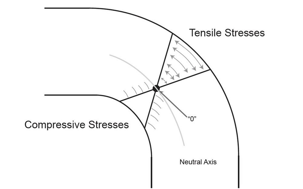
FIGURE 2. Each bend has tensile stresses and compressive stresses. The neutral axis is where the stress is theoretically at zero.
The tonnage necessary to bend 1 ft. does not double at 2 ft. but instead may increase by two-and-a-half to three times. As the required force to bend increases, the material’s ability to flow decreases, and the inside bend radius transitions from a floated radius to one that conforms more to the radius on the punch nose.
When bending at low pressure, the metal is flexible enough to be shaped by the die opening to create the bend radius. This allows us to develop a percentage value that we can use to establish an inside bend radius value without bending a test coupon.
What happens when the forming pressures are high? As the die opening narrows and/or the material’s yield and tensile strength increase, the forming tonnage increases. When the tonnage force increases, the ability of the material to flow and form as a percentage of the die opening decreases. Instead, the material begins to conform to the punch nose radius.
This is where ductility starts to play a role. Under higher forming pressures, highly ductile material eventually bends tightly around the punch nose radius, making the punch nose radius the dominant factor in determining the bend radius.
Calculating Tonnage Requirements
The more significant the tonnage is, the greater factor it becomes in the transition of the inside bend radius. There are many ways to calculate the tonnage required to bend sheet metal or plate. The two that follow are well-established equations calculating the forming tonnage for the total bending length, or the “point of interest,” as discussed last month. Both tonnage formulas are very good, though neither will ever be perfect.
Forming Tonnage = (Bend Length × Material Thickness2 × Tensile Strength) / (Die Opening × 1.5)
Note that in this first formula, the bend length is in inches and the tensile strength is measured in tons per square inch. Also, the shape of the die doesn’t matter. It could be a common V die, acute V die, or channel die; it won’t make a difference. It’s the width, or opening, of the die that matters.
This second formula calculates the required tonnage by the inch. To calculate the tonnage, multiply the result by the bend length.
Tonnage Per Inch = {[(575 × Material Thickness2 )/ Die Opening] / 12} ×
Factor for Material Type × Factor for Forming Method

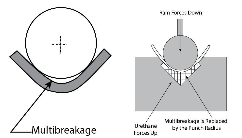
FIGURE 3. Large-radii bends often experience a phenomenon known as multibreakage, where a smaller leading radius “breaks away” and forms below the punch. Using a die with a urethane pad helps counteract this effect.
As for the forming method, air bending (central to the current discussion) is the baseline at 1.0. If you’re bottoming, the factor can be 5.0 or greater; and if you’re coining, the factor could exceed 10.
Regarding the factors for material type, 60,000-PSI cold-rolled steel is our baseline, with a factor of 1.0; 304 stainless steel has a factor of 1.4; and 5052-H32 aluminum has a factor of 0.5. To determine a material factor that’s not listed here, you can just compare it to that 60,000-PSI baseline for cold-rolled steel. So, if your material’s tensile strength is 120,000 PSI, the material factor would be 2 (120,000/60,000 = 2).
Stress, Strain, and the Curve
The stress-strain curve (see Figure 1) shows a material’s behavior when increasing force (tonnage) is applied. Stress is the ratio of force to cross-sectional area, while strain is the ratio of the change in length from its original dimension.
When bent, metal experiences a stress distribution that is tensional on the outside of the bend radius and compressional on the inside of the bend radius. The neutral axis is a line within the sheet metal where the stress is theoretically zero (see Figure 2). There are many types of strain, tensile and compressive being just two. However, all of them significantly influence the part’s dimensional accuracy.
Strain Distribution and Peak Strain
Finnish researchers at the University of Oulu’s Materials and Mechanical Engineering department found that both the bend angle and tool radius play a huge role in stress and the moment of bend. For most materials, the change in the moment is gradual, increasing at a constant rate as bending force is applied and the workpiece penetrates the die space; it keeps increasing until the outside bend angle reaches about 40 degrees.
This means that, at first, the bend’s outside surface and the neutral axis are moving toward the punch radius due to thinning. After 40 degrees of bend angle, they move away from the punch, and if the punch has a radius large enough, you will begin to see multibreakage (see Figure 3). This is where we see the loss of contact between the tool radius and the bend line.
As penetration into the die space and increased bend angle occur, we reach the point of peak strain, which then starts to decrease. As the researchers put it, this can be “attributed to the wrap-around and the consequent change in the loading scheme.”
So, what does this have to do with our topic at hand? At the start of the bending process, the deformation is mainly localized at the centerline; the material is flowing. But as the strain increases, the inside radius in the sheet decreases. At some point, the peak strain is reached, and we find that the inside bend radius becomes equal to that of the punch nose radius as the sheet wraps around the punch. So, increased tonnage leads to higher stress along the bend line. Higher stresses are required to deform the material, and material flow becomes less pronounced as a result.
Back to the Abyss?
The abyss is starting to stare back again, isn’t it? Don’t worry; we are on the path and doing fine. Soon, we will pull all this together. We’re reviewing all these factors because they affect how metal bends on the press brake. When we apply that knowledge, we can make better parts with fewer issues.
Next month, we will examine a few more aspects before summarizing their effects on the moment of bending and the transition of the inside bend radius. This will help explain why, as a bend line gets longer, the tonnage increases exponentially while progressively changing the bend radius and your calculations. I know that abyss is staring at you, but bear with me. It’s worth it.
Reference
A. Pokka, V. Kesti, L. Troive, and A. Kaikalainen, “Development of the cross-section moment in air-bending,” Materials Research Proceedings, Vol. 41, p. 1027-1037, 2024.
The article is reproduced from: https://www.thefabricator.com/thefabricator/blog/bending/air-bending-long-on-the-press-brake-part-ii
ABOUT THE AUTHOR:
Steve Benson
ASMA LLC
-----------------------------------------------------------------------------------------------------------------------------------------
We are FABMAX company!
We offer all kinds of press brake tools: punches and dies for press brakes with various fastening systems,
such as: Amada Promecam, Aliko, Yawei, Durmazlar, Baykal, Accurl, Accurpress, LVD, Darley, Naso, Wila, Trumpf, Rolleri, UKB, Eurostamp, etc...
We are always welcome you to discuss with us about the toolings!
 Alibaba.shop
